Viewing entries in
"Plating"

A Little Plate Talk

1 Comment

A Little Plate Talk

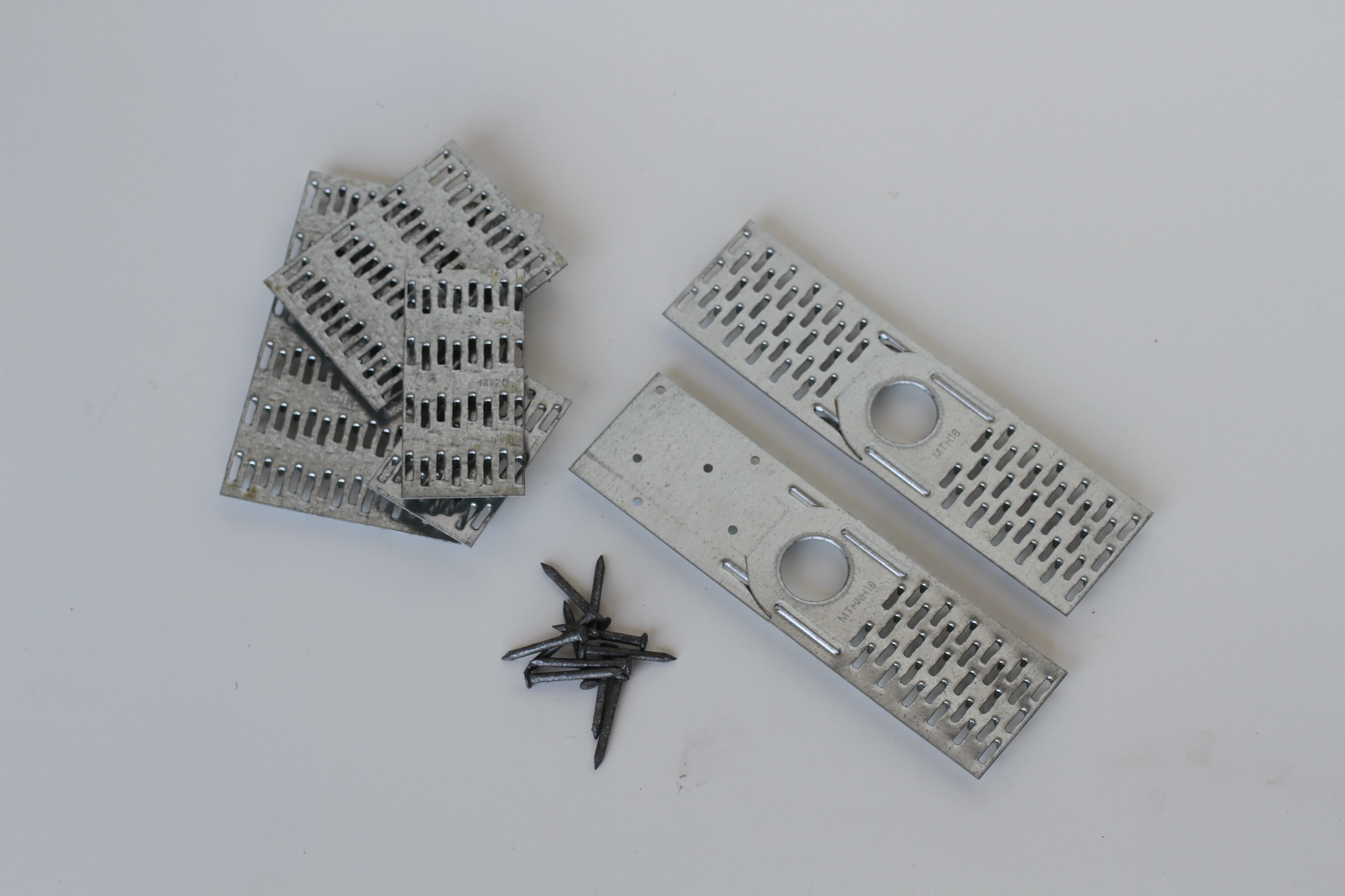
The typical US truss connector plate is made from Grade 40 structural steel that has been coated with zinc. “High strength” plates are made from Grade 60 steel. In the US, the coating of “typical” plates is called G60, meaning that for every square foot of metal surface, the zinc coating weighs at least .60 ounces. How thick of that coating? Between five and six ten thousandths of an inch.

Is there any 20g plate that weighs exactly a pound? Both the 20g 6x14 and 7x12 are close. A pound of plates (20g) is 87 square inches.

G90 plates

In Canada, where thicker zinc coats are the norm, the “standard” coating is G90.  G90 plates cost a little more than “standard” G60 plates in the US.

G185 plates

These plates are sometimes specified in corrosive environments and when specially treated lumber is used. These plates are available in a limited number of sizes, and are about twice the cost of G60 plates.

Stainless steel plates

These plates are also specified for some corrosive environments, come in a very limited number of sizes, and cost 8-10 times more than G60 plates.

Bevel Plates

Bevel plates are available in a small number of sizes and are ideal for certain top chord bearing floor truss situations.

T-plates

The T-plate is simply a T shaped plate that is to be used to increase the top chord bearing reaction limit on certain 4x2 top chord bearing joint configurations (without a block).

Hinge and Half-Hinge plates

Hinge plate are used for manufactured housing trusses and to eliminate the need for a separate “cap truss.” The “half hinge” is used at the peak of hinged trusses to connect the two chords coming together.

1 Comment

Plating Again - Details of Fabrication Tolerance

1 Comment

Plating Again - Details of Fabrication Tolerance

The first part of this article borrows heavily from the excellent article “Reviewing Metal-Plate-Connected Wood Truss Submittal Packages” by William Bolduc, PE, SE that appeared in ICC eNews. The MiTek information is current through Version 7.2.4 released in May, 2010. Thanks to JM for asking the questions that led to this article.

The strength of trusses is affected significantly by the quality of:

·         the position of the plate on the joint

·         the embedment of the teeth into the wood

·         the quality of the lumber at the contact area under the plate

TPI 1-2002 introduced a new factor and new quality control procedures to better account for real-world conditions and the likely possibility that the items mentioned above will affect the strength of trusses. TPI 1-2007 further clarifies and refines how to use the new factor and quality procedures. Under these codes, each truss manufacturer must now establish “fabrication tolerances” and have the truss design drawings engineered to match the fabrication tolerance used in the manufacturing of trusses.

TPI 1-2002 states that either the fabrication tolerance or the quality control factor (Cq) must be stated on each truss design drawing. TPI 1-2007 requires only the fabrication tolerance be stated on each truss design drawing.

What’s the “right” Fabrication Tolerance?

There is no single correct value. It depends on the quality control procedures used by the truss manufacturer. The fabrication tolerance may be any value from zero to 30 percent (or even higher.) What is important is that the fabrication tolerance shown on the truss design drawings matches (or exceeds) the fabrication tolerance used by the truss manufacturer for their quality control procedures. The third-party agency that audits the quality control procedures used in the truss plant must also agree that the quality procedure matches the fabrication tolerances shown on the truss design drawings.

Typically, truss manufacturers will use a higher tolerance for roof trusses than for floor trusses because of the greater geometric complexity of roof trusses and in recognition of the fact that the roof truss manufacturing process requires placement of the truss plate on the underside of the truss during fabrication. If the fabrication tolerance is less than 20 percent for roof trusses or 11 percent for floor trusses, the TPI 1-2002 (Section 3.2.4.2) requires that the fabricator provide to the approved inspection agency, or through other means, “justification” for the lower fabrication tolerance. ANSI/TPI 1-2007 does not have this requirement.

Fabrication Tolerance in MiTek Software

The TPI QC Fabrication Tolerance % (Fab Tol) in entered directly in the Plate Options section and will only affect plating if TPI 2002 or TPI 2007 are used. “Out of the box” this is set to “20.” To some extent Fab Tol replaces the Plating Tolerance (Plt Tol) setting, which has been around for a long time. Plt Tol, which is entered in 16ths of an inch, literally reduces the effective size of the plate in all directions for calculation purposes. So for example, if you have a Plt Tol of “100” (1”) and you have a 6x10 plate, the program would be use the 6x10 but calculating the plate as if it were a 4x8. Because they do different things, if Fab Tol and Plt Tol are both used, they are usually additive. Here are the square inches of plates I found on a common truss run with various settings. This should not be interpreted as being representative of the overall effect of these controls – just an example of the fact that they operate independently.

Plating Tolerance    Fabrication Tolerance  Square Inches Plate

0                                  0                                  248

4                                  0                                  264

0                                  20                                280

4                                  20                                284


The Incremental Decrease of Fabrication Tol % (Inc Dec) factor gives the program a better chance of plating all joints. Rather than “failing” a joint that cannot meet the desired Fab Tol, the program reduces the Fab Tol for that joint by the value specified in this control. If the program still cannot plate the joint, it reduces the value again by the same amount and so on until a plate works. The bigger the number the quicker the program will find a plate. The smaller the value, the slower the plating routine will run but with a better chance of allowing for some defects at the joint. If the Fab Tol is reduced by this method, a note will appear on the Engineering Drawing specifying the reduced Fabrication Tolerance for that joint. The TPI QC Plate Rotational Tolerance (degrees) of 10 degrees is specified in the TPI 2002 and 2007 codes and this is the program default. You can use a different value (than 10 degrees) based on your Quality Assurance program. The smaller this value, the smaller the plates, but for any value below 10 a note specifying the Rotational Tolerance will be shown on the Engineering Drawing. If the value is left at 10 degrees, no note is printed.

1 Comment

What Can Be Done With Plates

1 Comment

What Can Be Done With Plates

When I taught a class called “Advanced Features of MiTek Software,” one of the modules reviewed all the things you can do with plating. I found then and still find today that customers don’t always realize how much control they have. What we’ll cover here will be some basics – we won’t attempt to do training and we won’t attempt to get into the nitty-gritty engineering stuff either. I want to cover the basics of “what’s out there” so you get a sense of some of the things you can do.

Multiple Plate Inventories

Most plants use a single inventory that includes all the plates are usually stocked. But you don’t have to limit yourself – you can be more creative than that. There is a “All Available MiTek Plates” inventory that ships with the software. That comes in handy if you have a particularly difficult plating situation and just want to see if ‘any plate known to man’ will work. You can, if you wish, create a separate inventory for roof trusses and floor trusses. This is especially easy to do as the program allows a place for a separate inventory for roof trusses and floor trusses – most plants simply plug the same one in for both. You can actually set up any special inventory you want, and then apply it on a job by job or a truss by truss basis.

Temporarily Out of Stock

When you run out of a plate, you can simply uncheck it in the master plate list (which shows all plates in all inventories.) This takes it temporarily out of consideration from any inventory that the plate is part of. When you get your next shipment, simply “recheck” the plate to reinstate it.

Controlling Minimum Plate Sizes

When the MiTek program begins to analyze for plating, it identifies each joint by the combination of members coming into is. Knowing the joint type (visible in Plate Editor) allows you to modify the minimum, plate sizes to your own standards. For example, a peak plate for a Fink truss with 2x4 chords is a C-C-W-W and minimum sizes can be set for different span ranges. Different plate minimums are also associated with different chord sizes. Setting plate minimum sizes to what your shop actually uses is beneficial both in correctly costing the truss and in making sure that the sealed drawing matches the built truss – which can help a lot if the building inspector is taking a close look at things.

Controlling the Plate Orientation

Ever see a plate rotated a certain way and wonder - “Why?” Each joint type has a ranked list of “acceptable” orientations. The program tries the smallest plate in the first orientation, and if that fails it tries each of the other orientations in order. If they all fail, the next plate size is tried and this continues until the joint plates. By changing the order of the ‘preferred’ orientations, you can almost always have the program orient the plates they way you want without having to resort to Plate Editor.

Centering of Plates

Several settings work in concert to make plate fall in the “center” of the joint. This is done because it is considered more likely that a production worker will place a centered plate correctly than an “non-centered plate.” But is this still the right way to go when the production worker has the benefit of lasers to help him place the plate correctly? Reduce the “Sq. in. saved before using non-centered plates” in Plate Options to reduce the upsizing of plates done to locate them at the center of the joint.

Last Resort Options

If you have one of those trusses that is just hard to get to plate, remember this trio of Plate Options may at least help you get to the next step: “Plate even if overstressed” allows the plating routine to go forward, even if the truss fails. “Allow overlapping plates” will at least see if the program can find a solution – even if the plates are overlapping. “Allow perimeter violations” allows you to see how close you are to getting a plate to work without plating outside of the perimeter of the truss. With each of these situations, good judgment and close consultation with your ‘review and seal’ engineer is essential.

1 Comment